Flexible RVT_ELEC_01101 Testing Engine | Latest RVT_ELEC_01101 Dumps
Wiki Article
What's more, part of that ExamDiscuss RVT_ELEC_01101 dumps now are free: https://drive.google.com/open?id=1Sr5uhFzAFTWlsrAi3Z2XlHQfSDvnACa-
Our RVT_ELEC_01101 Study Materials are recognized as the standard and authorized study materials and are widely commended at home and abroad. Our RVT_ELEC_01101 study materials boost superior advantages and the service of our products is perfect. We choose the most useful and typical questions and answers which contain the key points of the test and we try our best to use the least amount of questions and answers to showcase the most significant information.
Autodesk RVT_ELEC_01101 Exam copyright Topics:
| Topic | Details |
|---|---|
| Topic 1 |
|
| Topic 2 |
|
| Topic 3 |
|
| Topic 4 |
|
| Topic 5 |
|
>> Flexible RVT_ELEC_01101 Testing Engine <<
Latest RVT_ELEC_01101 Dumps, RVT_ELEC_01101 Related Exams
If you want to do something different and stand out, you should not only work hard but also constantly strive to improve including education qualification and career certificate. RVT_ELEC_01101 exam simulations files can help you obtain an IT certification. As we all know IT exam cost is very high, most people have to try more than one time so that they can pass exam. If you prepare based on our RVT_ELEC_01101 Exam Simulations files, you will feel easy to clear exam once certainly.
Autodesk Certified Professional in Revit for Electrical Design Sample Questions (Q60-Q65):
NEW QUESTION # 60
Refer to the exhibit.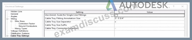
An electrical designer models a cable tray in a project and decides to check the box (or Use Annot. Scale tor Single Line Fittings and change the Cable Tray Fitting Annotation Size to 1/8" (3 mm).
What is the result?
(The image is presented m Imperial units: 1 In = 25 mm (Metric units rounded].)
- A. All cable tray fittings in the project change per the new settings when a views detail level is set to Fine.
- B. New cable tray fittings use the new settings after the change.
- C. All cable tray fittings in the project are changed per the new settings.
- D. New cable tray fittings use the new settings in views set to 1/8" (3 mm) scale.
Answer: C
Explanation:
In Autodesk Revit MEP, the Electrical Settings dialog box contains project-wide configuration parameters that affect all electrical systems, including Cable Tray Settings. This dialog allows users to control annotation scales, fitting symbols, and text size for documentation purposes.
The option labeled "Use Annot. Scale for Single Line Fittings" determines whether the cable tray fittings' annotation graphics automatically scale according to the view's annotation scale. When this box is checked, the annotation symbol size for fittings adjusts proportionally to the scale of the view.
Similarly, "Cable Tray Fitting Annotation Size" defines the annotation size for cable tray fittings in single-line representations (schematic views or simplified plan representations). Changing this parameter (for instance, from ¾" to ⅛") modifies the visual representation globally for all cable tray fittings in the project, since the Electrical Settings dialog is a project-wide configuration, not a per-instance or per-view override.
According to the Autodesk Revit MEP User's Guide (Electrical Systems - Cable Trays):
"Electrical settings define how cable trays and conduit are displayed throughout the project. Any change made to these settings, such as annotation size or use of annotation scaling, affects all related fittings and components in the project model." Therefore, once the designer checks the box for Use Annot. Scale for Single Line Fittings and changes the Cable Tray Fitting Annotation Size to 1/8" (3 mm), all cable tray fittings across the entire project will update to reflect these new settings.
NEW QUESTION # 61
Refer to the exhibit.
- A. Properties > Edit Type > Single Line Symbology
- B. Object Styles > Conduits > Rise/Drop > Single Line Symbology
- C. Project Browser > Conduits > Conduits with Fittings > Single Line Symbology
- D. Electrical Settings > Conduit Settings > Rise Drop > Single Line Symbology
Answer: A
Explanation:
In Autodesk Revit MEP, conduit systems can be represented in plan views using either detailed or single-line symbology. The Single Line Symbology display setting is used for schematic or simplified representations - often in electrical riser or distribution diagrams.
The setting that controls whether conduits display in single-line or detailed form is found in the Type Properties of the conduit family, not in Object Styles or Electrical Settings. Specifically, it is accessed by selecting a conduit in the model and navigating to:
Properties Palette → Edit Type → Single Line Symbology
From there, users can define how fittings, rise/drop symbols, and conduits themselves are represented in single-line schematic mode. Adjusting this type parameter affects the graphical display for that conduit type throughout all applicable views where single-line graphics are used.
According to the Autodesk Revit MEP User's Guide (Electrical Systems → Conduit Systems section):
"The conduit type properties define the graphical representation in single-line drawings. By editing the Single Line Symbology in the Type Properties dialog, designers control how the conduit and fittings appear in plan views." This parameter is especially important in electrical documentation where simplified representations are required for coordination and electrical diagrams.
NEW QUESTION # 62
Refer to exhibit.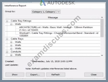
An electrical designer runs an interference check and reviews the Interference Report.
How can the designer select the cable tray fitting referenced in the interference to resolve the clash?
- A. Click Export, expand Cable Tray Fittings, and select Channel Horizontal Bend: Standard.
- B. Double-click the fitting that appears in the list.
- C. Select the row with the cable tray fitting, and activate IDs of Selection.
- D. Select the row with the cable tray fitting, click Show, and select the fitting.
Answer: D
Explanation:
When performing an Interference Check in Revit, the Interference Report dialog is generated. This report lists all interfering elements found. To select or locate a specific element-such as a cable tray fitting-the designer must use the Show command.
The official workflow from the Revit documentation clearly states:
"To see one of the elements that is intersected, select its name in the Interference Report dialog, and click Show. The current view displays the problem." This confirms that selecting the row that lists the interfering cable tray fitting and clicking Show will highlight and activate the view containing the clashing element-allowing it to be modified or moved to resolve the conflict.
This means the designer must:
Click the row containing the cable tray fitting in the Message list.
Click Show to highlight and locate it in the model view so the clash can be addressed directly.
This reference explicitly confirms that Show is the correct method to select the clashing cable tray fitting from the interference results in order to resolve the conflict.
NEW QUESTION # 63
Refer to exhibit.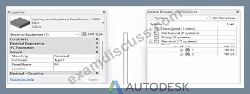
To which panel Is Panel P4 circuited?
- A. Panel P 2
- B. Panel P 5
- C. Panel P 3
- D. Panel P 1
Answer: A
Explanation:
In Autodesk Revit MEP Electrical Design, the System Browser is used to analyze and verify electrical systems, including panelboard connections, circuit hierarchies, and connected loads.
From the exhibit, the Properties palette shows that the selected equipment is a Lighting and Appliance Panelboard (208V MLO, 100A), named P4. To determine the parent panel that feeds Panel P4, we refer to the System Browser, which organizes the entire electrical distribution network hierarchically under the Electrical discipline.
In the System Browser on the right, under the Electrical category, we can observe that Panel P4 is nested directly under Panel P2. This organization indicates that P4 is circuited to (or fed from) Panel P2.
According to the Revit MEP 2011 User's Guide, Chapter 4, "Electrical Systems-Using the System Browser," it states:
"The System Browser displays electrical systems in a tree structure. Each subpanel or device listed beneath a main panel is connected to that panel through an electrical circuit. When a panelboard appears under another, it indicates the subpanel is fed from that parent panel." This is further reinforced in Smithsonian Facilities Revit Electrical Template Documentation (April 2021), Section 8.3 "Documentation Views," which describes:
"Panel schedules and browser hierarchies show the distribution sequence. Subpanels appear indented beneath their source panel, indicating electrical dependency and circuit assignment." Therefore, by interpreting both the Revit interface and Autodesk's documentation, Panel P4 is a subpanel connected to Panel P2, confirming that its electrical feed is assigned from Panel P2.
Final Verified answer: B. Panel P2
Reference Sources:
Autodesk Revit MEP 2011 User's Guide, Chapter 4 - Electrical Systems and the System Browser Smithsonian Facilities Revit Template User's Guide, Section 8.3 - Electrical and Fire Alarm Templates: Documentation Views
NEW QUESTION # 64
Refer to exhibit.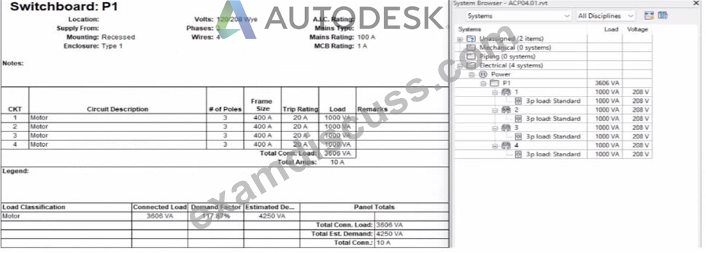
An electrical designer expects the total connected load on the switchboard to be 4000VA. but Revit Indicates a total connected load of 3606VA. What Is the cause of the discrepancy?
- A. The Motor demand factor is configured to adjust the connected load.
- B. The connected loads are set to a different voltage than the switchboard.
- C. Sum true load and reactive load is selected in Electrical Settings.
- D. Load is connected through the switchboard's feed through lugs.
Answer: A
Explanation:
In the exhibit, the designer expects the total connected load to equal the sum of the 4 motor loads:
4 motors × 1000 VA each = 4000 VA expected
However, Revit is showing a Total Connected Load of 3606 VA instead.
This difference occurs because Revit applies Motor Demand Factors automatically when a load classification is set to "Motor." Demand factors modify the total connected load based on electrical engineering rules.
Revit documentation confirms:
"Assign demand factors to load classifications."
"Demand loads can be shown on panel schedules."
In the exhibit, the Load Classification shows Motor with a Demand Factor of 117.87%, which modifies the connected load values in the switchboard totals.
Revit is therefore calculating the effective connected load based on the applied demand factor, not a simple arithmetic sum. That is why the panel's connected load number ≠ 4000 VA.
NEW QUESTION # 65
......
You can also be a part of this wonderful community. To do this you just need to pass the RVT_ELEC_01101 certification exam. Are you ready to accept this challenge? Looking for the proven and easiest way to crack the Autodesk RVT_ELEC_01101 Certification Exam? If your answer is yes then you do not need to go anywhere. Just download ExamDiscuss Autodesk Certified Professional in Revit for Electrical Design exam questions and start Autodesk Certified Professional in Revit for Electrical Design exam preparation without wasting further time.
Latest RVT_ELEC_01101 Dumps: https://www.examdiscuss.com/Autodesk/exam/RVT_ELEC_01101/
- RVT_ELEC_01101 Valid Test Discount ???? RVT_ELEC_01101 Study Tool ???? Reliable RVT_ELEC_01101 Source ???? Search for ⏩ RVT_ELEC_01101 ⏪ and easily obtain a free download on { www.easy4engine.com } ????New RVT_ELEC_01101 Test Topics
- RVT_ELEC_01101 Exam Papers ???? RVT_ELEC_01101 Reliable Exam Pdf ???? RVT_ELEC_01101 Study Tool ???? Immediately open ⮆ www.pdfvce.com ⮄ and search for ➡ RVT_ELEC_01101 ️⬅️ to obtain a free download ????Reliable RVT_ELEC_01101 copyright
- Here's the Easiest and Quick Way to Pass Autodesk RVT_ELEC_01101 Exam ???? Immediately open [ www.vce4dumps.com ] and search for 「 RVT_ELEC_01101 」 to obtain a free download ????RVT_ELEC_01101 Customizable Exam Mode
- How Autodesk RVT_ELEC_01101 Practice Questions Can Help You in Exam Preparation? ???? Search for ➡ RVT_ELEC_01101 ️⬅️ and obtain a free download on “ www.pdfvce.com ” ????RVT_ELEC_01101 Valid Test Discount
- RVT_ELEC_01101 Valid Test Discount ???? RVT_ELEC_01101 Valid Test Discount ???? RVT_ELEC_01101 Dump Check ???? Easily obtain free download of [ RVT_ELEC_01101 ] by searching on [ www.examdiscuss.com ] ????RVT_ELEC_01101 Latest Test Labs
- Here's the Easiest and Quick Way to Pass Autodesk RVT_ELEC_01101 Exam ???? Search on ☀ www.pdfvce.com ️☀️ for ▶ RVT_ELEC_01101 ◀ to obtain exam materials for free download ????RVT_ELEC_01101 Latest Test Labs
- RVT_ELEC_01101 Valid Test Discount ???? Reliable RVT_ELEC_01101 Exam Preparation ???? RVT_ELEC_01101 Study Tool ???? Search on 【 www.practicevce.com 】 for 【 RVT_ELEC_01101 】 to obtain exam materials for free download ☝Reliable RVT_ELEC_01101 copyright
- RVT_ELEC_01101 Actual Cert Test - RVT_ELEC_01101 Certking Torrent - RVT_ELEC_01101 Free Pdf ???? Search for ⏩ RVT_ELEC_01101 ⏪ and obtain a free download on { www.pdfvce.com } ????RVT_ELEC_01101 Valid Test Discount
- RVT_ELEC_01101 Dump Check ???? RVT_ELEC_01101 Books PDF ???? RVT_ELEC_01101 Books PDF ???? Search for 「 RVT_ELEC_01101 」 and download exam materials for free through [ www.examcollectionpass.com ] ????Pdf RVT_ELEC_01101 Torrent
- 100% Pass Quiz 2026 Autodesk Pass-Sure RVT_ELEC_01101: Flexible Autodesk Certified Professional in Revit for Electrical Design Testing Engine ???? Go to website ⇛ www.pdfvce.com ⇚ open and search for ➽ RVT_ELEC_01101 ???? to download for free ????New RVT_ELEC_01101 Test Topics
- RVT_ELEC_01101 Dump Check ???? New RVT_ELEC_01101 Dumps Book ✴ Pdf RVT_ELEC_01101 Torrent ???? The page for free download of ➽ RVT_ELEC_01101 ???? on 【 www.testkingpass.com 】 will open immediately ????RVT_ELEC_01101 Books PDF
- lewisenhb303041.bloggactif.com, owaindgrx699680.answerblogs.com, zoeadzf183896.activablog.com, brianimio345690.atualblog.com, henridzef751605.wikifiltraciones.com, bookmarkinginfo.com, joycehwna672513.blog2news.com, social-lyft.com, iowa-bookmarks.com, nicolevsfe554021.blogsvila.com, Disposable vapes
BONUS!!! Download part of ExamDiscuss RVT_ELEC_01101 dumps for free: https://drive.google.com/open?id=1Sr5uhFzAFTWlsrAi3Z2XlHQfSDvnACa-
Report this wiki page